IGBT FF1000R17IE4
Contents |
Download
Identification tool
The parameter extraction has been done by means of a Matlab-PSpice optimization tool, the POPM (Parameter Optimizer for Pspice Models) which you can find here. It is a user-friendly Graphic User Interface (GUI) that you can use on your own.
Tests performed
Static
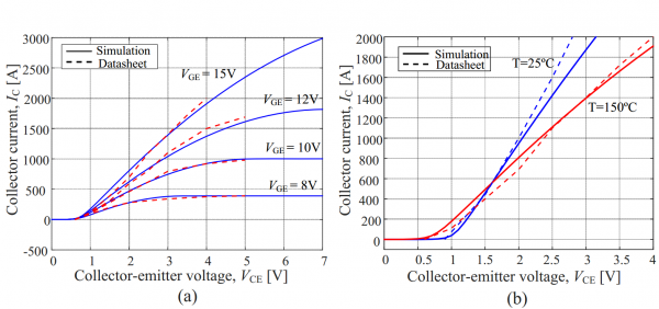
Fig. 1 reports the comparison between the datasheet information and the simulated static output characteristics. More precisely, Fig. 1 (a) shows the IGBT output characteristics at 150ºC for the following gate voltages: VGE=8V, 10V, 12V and 15V. Fig. 1 (b) displays the simulated static output characteristics as a function of temperature (i.e., T= 25ºC and T=150ºC) for a given gate voltage (VGE =15V).
 |
Dynamic
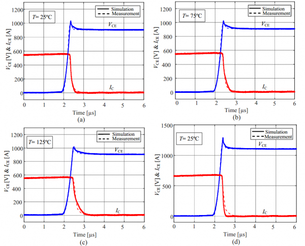
Fig. 2 (a) shows the comparison between measured and simulated turn-off waveforms at the following testing conditions: IC=560 A, VDC=900V and T=25C. The comparison between the PSpice simulation and experimental results validating the temperature-dependent IGBT model under inductive switching conditions are shown in Figs. 2(b) and 2(c) at 75ºC and 125ºC, respectively. Fig. 2 (d) shows the comparison between the experimental curves at different current and voltage levels (IC=670 A, VDC=1100V).
 |
Shortcircuit
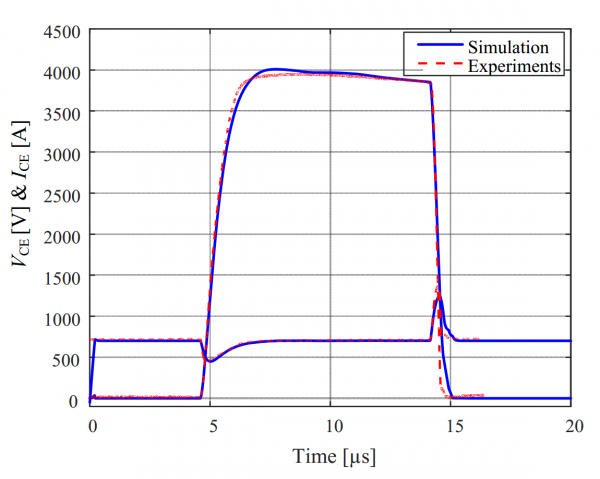
The nominal short-circuit conditions for experimental analysis were: DC-link voltage VDC=700V, gate voltage VGE=15V, gate resistance Rg=1.2 , short circuit time tsc = 10 us and stray inductance Ls=40nH. Fig. 3 shows the comparison between the simulation waveforms and measured waveforms during a short-circuit type 1 event.
 |

